Showing posts with label maritime. Show all posts

Friday, July 9, 2021

H.M.S. Prince -The Final Modification/ Rex Stewart


It is not surprising to find builders frustrated when it comes to rigging. In my forty-plus years as a professional, this was (and is) one of the principle subjects many have been at odds with. Not just with themselves, but with other professionals and hobbyists.

Many will argue that 'sailing' ships are not attractive with sails because it 'hides' rigging. Yet one of the main factors for this system remains to be the 'sails'! And there is a method for bringing out the best in any model once the science is studied and worked upon. It doesn't happen overnight...And for those who claim they have expertise with this after building a few pieces; well that assessment is void.

Another argument/debate that comes to mind is the theory that ships were built without blueprints. That shipwrights calculated 'everything' in their head. That is sheer foolishness -and not to be embraced by anyone with commonsense. However, this is part of the maritime circles that continue this 'theory'.

Blueprints are the essence of the builder. Without them nothing is accomplished.

History, unfortunately has a universal way of hiding truth and I realize that the only viable way to discover (truth) is to divorce the politics and focus on the purity of research. Real answers are found when biases are quelled. One of the reasons I produce some of the most exciting models today is primarily due to sound doctrine and research from the sources I investigate. 


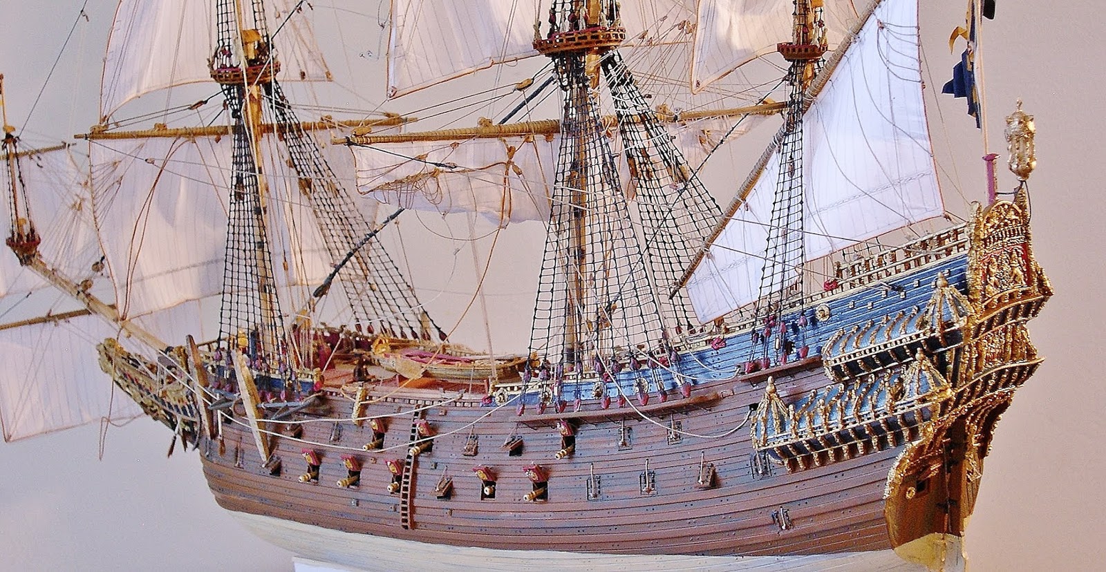
In this image, the rigging is not obscured by the sails...


Nor in this image.

Below, I show the dynamics of sail setting -where the variations bring realism to the subject. It's in this artificial form that my viewers (and collectors) find the perfect balance. However, this is predicated on research as to how ships appeared in wind under full and/or partial sail. 


With this focus in mind, I return back to rigging tables -exploring areas of rig that I found questionable relative to belay systems; especially at the quarter and mizzen decks. There seem to be much confusion in these two areas

There exist no drawings and/or paintings that clearly defines this. And of the contemporary work(s) I reviewed, I wasn't able to acquire correct fall lines that were compatible to the ship's design. That alone, pushed me to rewrite the script concerning their true location(s) from a logical stance. Of course I tossed 'debates' to the wind because those were distractions which was based on "cognitive dissonance". And of such I have, nor take no part.


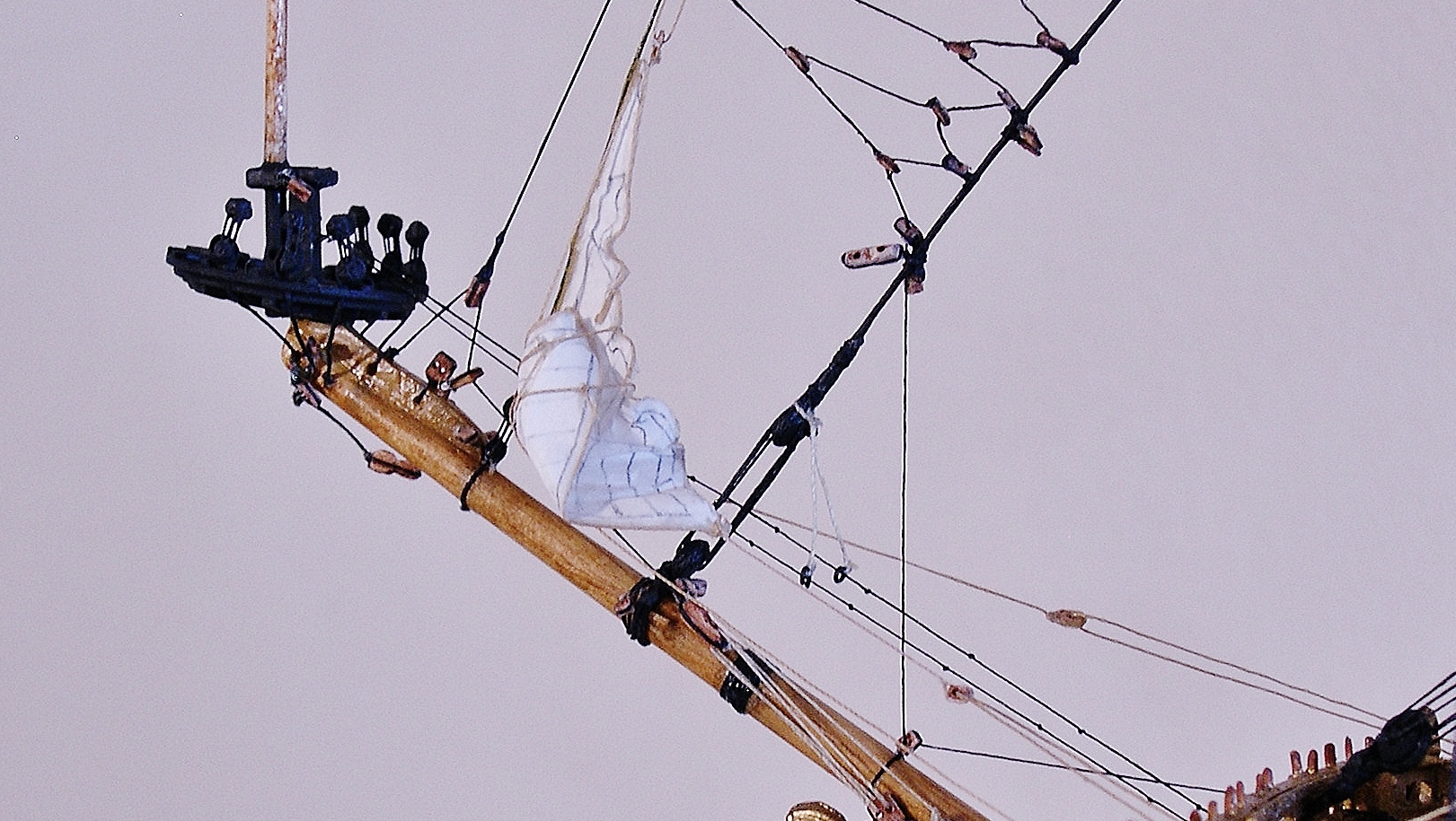
In this image I am resizing the plastic lateen sail which I will later customize from treated paper. I am also locating the various rigging points on this sail to transfer to the custom sail so that the lines will fall accurately to the belays pins on deck. Much of my concern are on the brail system, as I have not found any satisfactory model showing this to be compatible to the Prince design. There had to be leeway and room for hauling up this large sail so not to conflict with the large topsail above it.

Percival Marshall's 1937 plan is the best reference that makes any sense to this perculiar design of the poop and quarter decks. From his perspective, it made sense that the forward brails would lead from the spar to the last shroud and down to the belay pin rail 'within' the ship -not on the actual top rail as seen on many contemporary models. Builders are not taking the time to assess scale to embrace this truth. Percival , being notably famous for his engineering proved this finding to be correct...and it is shown on my model, in kind.


This waterline view show the lateen sail set in a swift breeze with the forward brails leading through the blocks and connecting with the blocks on the last shroud. Notice that there are no pins on any of the rail area at the main mast to the stern area where the ensign is flying.


Port stern profile showing the brail leads to the main shroud. The lateen mizzen sheets also fall to the pin rail within the quarter deck bulwarks (away from the guns). Based on scale, it would be impossible for crew to reach and effectively secure these lines to pins on top of the bulwark. However, at the forecastle such was possible as I have shown in prior images.


Before rigging is complete, gallery windows are prioritized; especially since some lines will conflict with gold leaf in those areas where shrouds, sheets, lanyards and braces are located. Not to mention the backstays and halyard tackles.


Here the gallery windows are displayed in good order -placed and readdressed with gold leaf. 


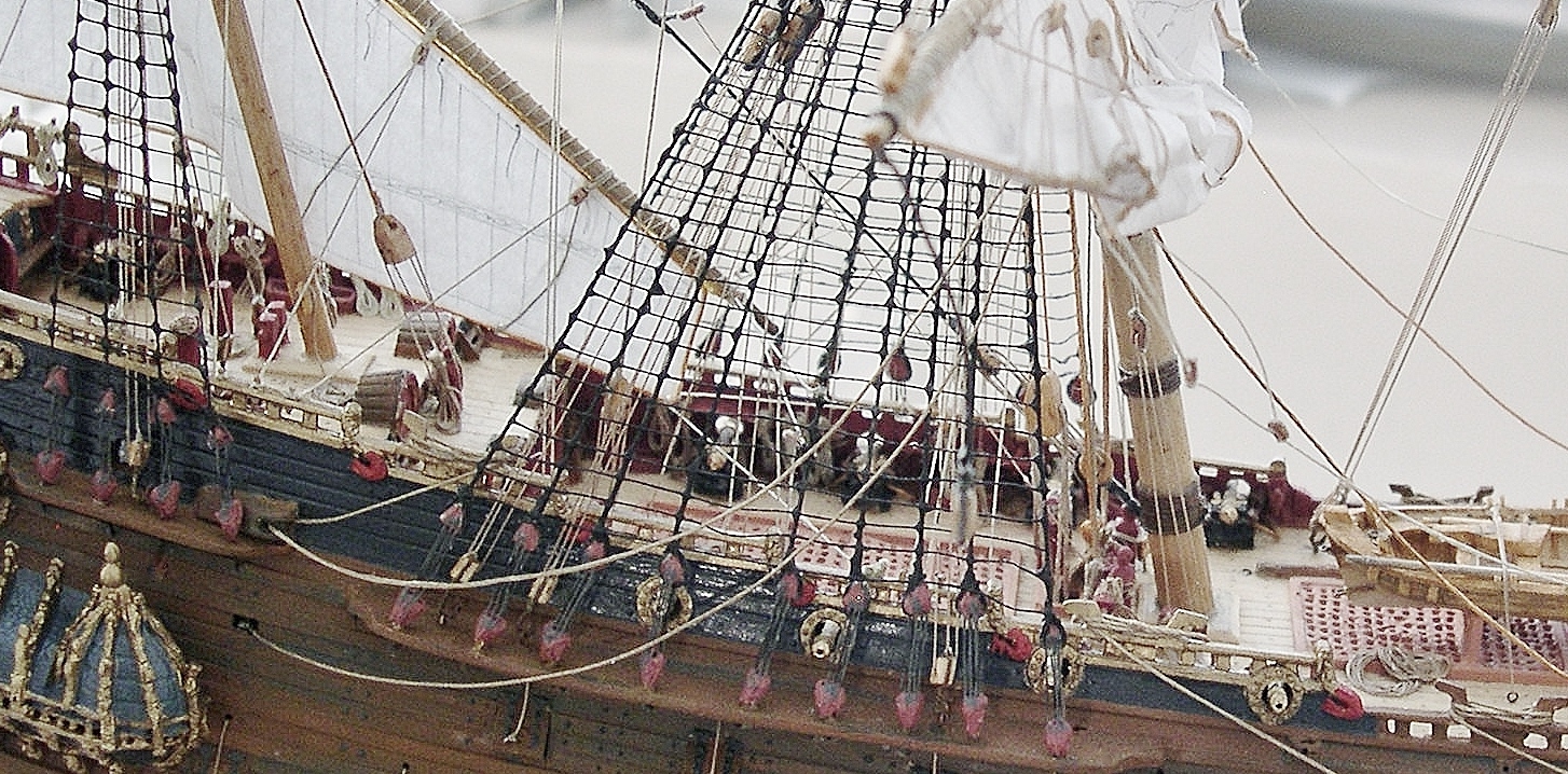
As aforementioned, lines should not conflict with each other -leading through and around the tops down to their proper pins without fouling (as shown in this image). Also, based on the railing system (and scale)...notice the pinrails at the companionway before the stairs. The lines are clean and fall there without fouling. Furthermore the scale of the bulwark rails are too high for any crew member to actually secure a line. In Admiralty models much of this is ignored -or was never considered, being that the primary focus was on the structure of the ship. This is conclusive based on the many profile drawings stored in museum archives. None show total belay processes (of any kind) from that era.

Even when VASA was raised, there were no factual documentation(s) conclusive to her rigging...None. Every aspect of rigging was actually explored in the 19th century and pieced together by scholars who visited various museums/libraries to obtain 'limited' data. These facts can be validated by another contemporary builder in his quotation below:


This builder place emphasis on the PRINCE model at the Science Museum in England. From his perspective it is worthy; but from a rigger's point of view, one has to question the findings... And, I duly agree from a curatorial view, misguided information should not be passed on to any generation seeking truth. It's wrong.

Below are the final images of the PRINCE which conclude this build. There will always be PRINCE models which will differ in presentation. No one model can claim accuracy; that's a fallacy. However, each model has its place because of its reputation -and this piece is no different. I just brought it to another level based on my experience and research. So now, I provide you, the viewer, these finale images.


As a professional, I take my work seriously which is shown in each and every model I produce. I take no shortcuts, but rather place as much detail possible in these work(s). This model is no exception.

For those who appreciate and seek this type of art, I can be reached at Caseships@yahoo.com or by phone 1-774-757-7137.

Thanks for viewing! 


Monday, April 26, 2021

British Warship HMS Prince -Art Of Modification/Part Five


In my last blog I spoke about not being too consumed in a build. It's always good to walk away when the mind touches upon frustration. Others will argue that it's 'healthy'...but there are consequences when attempting to force a thing.

I know only a few will heed my advice, and this will only rob those who are proud to not really digest what I'm writing. I didn't get here to this level shucking peanuts; I got here because I was 'willing' to read the literature of my forerunners to get the schematics of the process. I threw away the vanity and the politics to embraced the method and techniques. That's how hungry I was to be one of the best in what I do.

The above image show the detailed bow and anchor arrangement of the Classic Series -Airfix HMS Prince. The colors are subtle and not overworked -lending more attention to details while the goldleaf absorbs the viewer. Goldleaf doesn't overpower the model, but rather introduce a natural balance that the eye can absorb.

Below is my wood sculpted diorama titled "The Admiralty" which shows Phineas Pett among other subjects viewing and discussing a build for one their ships. It was one of his designs that brought the  H.M.S. Prince to sea.


Now that we're past the concepts of the hull, it's time to move on to the masts and rigging. Such is a complicated subject to discuss and I won't waste any time 'there'. My sound advice relative to it is simple: research, read, and research again. That's the jewel of ALL jewels -the ability to read and cipher between fact and fiction. The quality of my builds stem from the desire to compete with self. There is no good in competing with another; you take on their burden while attempting to finish yours. Also, don't make comparisons...just be honest about your assessments for which to make a point.

I made mention in one of my earlier blogs, that belay points were carefully studied before permanently securing the apparatus that was used for rigging this type ship. Furthermore, the locations had to be featured both on the masts/yards (and decks) where the falls would not foul the lines. In the process I noticed that the garnet tackle was wrongfully rigged on the top rail of the main deck. The scale would not place it there, but rather on the deck with a bitt piece (and ring bolt) which would secure the lower hooked block of the garnet. I found that the lashed spars would conflict with this tackle, so I made alternate bitts (port and starboard) and placed this apparatus portside.

In future photos I will show this detail...


 Another oversight was location of the fore course tack lines. I must concede that I flawed in my earlier builds of this vessel. Some experts stated that my lead and fall was accurate, but after seriously pouring over the plans, I realized I was just executing another fine-looking model. In this image I made bitts forward of the mainstay deadeyes for which to take on and secure the course tacks. This would in no way foul the other principle lines leading to their correct pins.

Below a model of the ST. GEORGE, 1701.... show those course tacks belayed in the same area. So, in essence, this is correct. As long as the lines are not overlapped on the same belay pin, the builder is fine. However, I did find that the topgallant and topsail bowlines overlapped; but those were of the same system and separate from the other functional lines. 


With that information secure, I'm now ready to rig...

As aforementioned, advance rigging takes much observation and preparation. The key to it all is to get the tackles on the mast (first); followed by the stays. Then, the rigging blocks must be attached as you work those two systems. Finally, the topropes and their tackles...Below are four images showing this process. Also, don't be particular about the outcome of the rigging process. Mistakes will occur; and don't take anyone's opinion as law. Things look good on paper (plans), but the true value of a thing arrives at the conclusion. Just because it's on paper, doesn't make it fact.

Build the model and you will discover your facts as you build. Sound and perfect advice to those who are willing to apply it.


The first application of rigging to PRINCE are the relieving tackles that are seen beneath the tops; followed by the stays. If the stays are applied first, then there's no need to focus on these tackles because it will conflict with the shrouds. Next is the garnet tackle(s) which is carried on the mainmast over the relieving tackles...After these are applied, move on to the stays and the webbed rigging above them known as the crowsfeet. That feature was to prevent the foot of the topsails from chaffing against the stays.


The final process before the shrouds are rigged is the sprit topmast backstay seen at the upper righthand; and the manropes (port and starboard) that lead from the forward bulkhead above the doors to the back stem of the topmast cap in the top...And last, the topmast topropes...and their tackles (that are rarely seen in good models).

The last two images show a partial finish of what I just mentioned -which will conclude in this blog before moving on to Part Six.


There is another important detail that need to be made mention of in the tackle system that can't be avoided. These are the truss tackles -a system of combined blocks and multiple rigging that was used to raise and lower the fore and main yards that were attached to parrels. These parrels expanded (with the help of the truss tackles) as they traveled over the wooldings as they were raised and lowered to the deck.

I've witnessed many builders producing detailed models, but shy away from the important details that would make the model authentic. A properly rigged model is worth its weight in gold.


In this photo I am reviewing details that I either missed, or need to revise. Such notes can be very time-consuming but worth the effort when it's effectively presented. It's not about being scholarly; it's about revealing buried information that go unnoticed...All the more reason these models are sought after by serious collectors.

As I continue to rig, I discover that more belay points/pins are needed. Early kit producers only gave generic/basic rigging leads; but omitted those that were essential to model building -especially on the PRINCE (and other 17th century ships). These lines were the various tackles, topropes, halyards, and proper bunts and leeches. Many models barely feature them -and these were the main systems for keeping the ship operational.

Below, I begin to address the rigging process by placing the miniature blocks on the masts and tops prior to rigging -and then secure the tackles before placing the shrouds.


Here, the tackles are applied, but more must be added. In  most contemporary models tackle falls aren't visible and must be found. The falls must be true to rigging standards relative to where those leads tie off. I've come to find that some of these lines were not on belay pins (as such) but on eyebolts with blocks that were in tackle form which were belayed on the lower rigging of those blocks -as shown behind the mainmast next to the companionway.

The image below show the early stage of shroud rigging...


Another application that I apply before continuing with the shrouds is rigging the jib. I usually draw out a rough sail schematic in lue of making a decision on how best the model will look to the viewer. I attempt to keep it authentic by mimicking sail formations on contemporary photos. However, I don't copy them to the letter, as such; but apply the basic generics (with my thought process) to give a more dramatical flow of canvas as if the ship was before the wind....But the process begin with the lead sails. The flow starts there.


 Here, I begin with the jib. I tried to make it as realistic as possible which included the folds and reefing.


Another common detail that seem to evade 17th century shipmodels are the crisscrossed lines on the lower and upper shrouds shown in this image. These were essential for strengthening the shrouds and were called catharpins. It seems difficult to rig these, but if the steps are applied faithfully (with concentration), it's fairly 'easy'.


I now leave the viewer with this image of the progress. However, I must be clear relative to these type models. Understand that there are no absolutes with the rigging process of these ships except that the applications were basic and true to the writings of the forerunners. It's those writings that I followed to conclude my spin on the process.

Over the years curators have falsely claimed that the rigging on the Prince was done during the time of the build; but the fact of the matter was when the actual model was purchased by the Kensington Science Museum in 1895 it was unrigged. The rigging was done in 1898 but wasn't found satisfactory and was subsequently redone correctly some years later. Yet, the question remained regarding belay systems that seem to have evaded those scholars of that time.

That being said, one can only speculate (with experience) where those systems began and ended on the conclusion of the lines themselves. So it's only fair to not assume but work those belay points where those lines would seem efficient for the crew member to work. I've done this to the best of my ability with all these models to the satisfaction of my collectors and scholars in the field.

Of course I've faced unprecedented scrutiny in the process, but that usually comes with the territory of painstaking research. This is what make my work what it is and I continue to push it forward with purity, not politics.

Airfix was true in designing this kit with what limited information it had -and I must concede that those engineers and draftsmen/women did a fine job of it. But with further global information, this model brings to bear even deeper revelations which, in part, make my work rare.

I appreciate the follow and hope you will be ready for 'Part Six' of this series.

Thanks for viewing!


Friday, February 19, 2021

H.M.S. Prince c.1670 -The Art Of Modification...Part Two


 As I sit here writing I can't help but to think how interesting my childhood was. I was adventurous and explorative. Always wanting to learn -whether from the classroom, the diverse community, or television. But the foundation of it all were my parents; primarily, my mother. In her was this immense wisdom that I later found in most women -and that ultimately put me over the top as a man, artist-craftsman, and father.

As such, I embraced history with an open mind -pushing away biases that was the pitfall to limited thinking. Instead, I absorbed every aspect of my profession down to the smallest details and embraced many, many cultures that helped it along...because in those cultures were missing pieces that made up what is viewed above -beauty.

In my early post on this subject I wrote about technique and staying in one's own lane. This principle I will continue to hammer home so that it will become evident (and fact) that we ALL have a purpose through the things we live and experience.

In the above image is the next stage is applied relative to taking plastic and simulating it to appear as wood. Yet, there are wood components in certain areas of the build.Al 


In this photo, natural wood components are seen -such as the interior deck props. These were fit in various locations to take on the wood cannons I made for the open gun ports. But prior to this I had to evaluate certain details and relocate them to their proper areas such as the deck furniture and bulkheads. The kit, though finely made, had issues which was unavoidable such as warping and mast displacement. Other factors included the bulkhead details such as adding to the carved pieces, removing windows and doors; and, substituting actual wood decks to take the eyebolts.  

The deadeye channels were no exception, they were completely replaced and knees which I hadn't  seen in any models. Knees were essential for strengthening the channels and lightening the stress when taking on the shrouds. At the fore channel such strengthening was mandatory when carrying the large stowed anchors.

Another missing element that I considered were the skids and/or fenders that were located amidship which ran down the side of the hull to the last wale at the waterline. These were very much part of the naval design -not just for British ships but for most seafaring nations. These skids and/or fenders prevented the boats from damaging the hull when being hoisted from and lowered into the water.


A closeup image showing the much notable skids/fenders. Also, notice the trunnels and planking about the topsides. This was done with a special pencil -one of the primary tools I use for both my models and dioramas. Every artistan have their arsenal of special tools needed to fit their line of work; and no two artists are alike because each use their tool(s) that are comfortable for his or her purpose. This is what makes work(s) 'original' and not a 'hard copy'. I encourage every novice artist/builder to explore materials and use them faithfully...because at the end of the day, the result will be yours. That advice you can take to the bank.

Research is beneficial at any level. The more study placed in a thing, expect better results!

I have invested countless hours in what I do and seldom keep logs. This current project is no exception. 

Usually I take my time (days or weeks) to scrutinize certain parts of the build before moving on to other areas. I will study other areas in preparation, but will refrain from touching anything until that particular space is finished -leaving no options to rework. This approach eliminate frustrations in the long run.

With the outside of the hull finished, I move on to the galleries. The windows would usually take a back seat until the lanterns are addressed...and yet, there are times when I would ignore the windows and move on to the interior work -such as the deck and cannons. The below images show the finished galleries.


The paints applied to this (and all my creations) are not straight from the jar; they are custom-mixed. Even the gold are applied in several variations -and gold leafed in certain areas for highlight. This process can take several weeks through experimentation.

To add better detail to gunports I work the lid ropes as shown in the following three images...


Next are the cannons which had to be scaled properly. The kit provided pieces that did not fit the overall appearance of the model. So, by trial and error, I made them from wood and secured them to wood platforms. This was followed by installing decks to cover the cannons and working up a template to make bulkheads and supporting deck furniture align correctly. Another set of photos support this below.


Viewing the image, the carriages and cannons are mounted below decks and the main deck is prefit to duplicate in wood. Also the plastic cannon/carriage are assessed to evaluate whether or not scaling is needed. The following photo show the conversion from plastic to wood on the quarter deck...


On this deck I relocated the grating as it is too close to the mizzen mast/slot. I noticed on various Prince models, this grating was omitted. It was inevitable to have these for dispersing smoke during cannon discharge.-especially since there were ten cannons within that enclosure.


In this image the main deck was also revised. It was here where I realized the scale of the guns were off relative to them clearing the bulwarks when being run in. Also the grating had to be slightly widened to support the boats without compromising the cannon. There was no room to place the grating that was supposedly behind the mainmast. In the plan drawn by noted British engineer Percival Marshall, no grating is shown.


Here is the scaled template I drafted to use throughout the build. The small markings on the side is the spacing of the shroud's ratlines in proportion to the crew members. There are more ratlines here than on conventional models


Another overview showing two separate templates for the build within the main deck waist. The lower template show the revised cannons in both run out and recoil position which has enough room to clear the bulwarks and gratings.

This conclude Part Two of the modification. There is much more to study before I move forward on this. However, from this assignment, I have come to learn more. I realize 'today' that Airfix models are a professional type model that is intend for those who are patient in the build for a museum type model of quality. There are many possibilities with this kit...and the plastic is of good quality to make changes that suit the builder.

Pieces are very small and to replicate them in another medium does require some skill. The drawback is missing pieces that can place a build 'on hold'...But for the experienced novice/professional, such parts can be customized.one can alter to be museum quality.

There is another factor that is overlooked with Airfix models; that is the scale. The company was precise in it, but the issue came up in debate on forums because builders couldn't match the scales based on the information given by the company. With a little investigative work I found that certain areas of each kit were either over-scaled or under-scaled. To alleviate that problem I picked two areas on the model that balanced in scale and reworked the entire model.

The two areas I studied were the steps, doors, and gun ports. I then made a crew figure template with additional deck furniture (to that scale) -giving me the precise measurements for all the fittings throughout the model. This procedure upgraded the Airfix kits to be a perfect 'one of a kind'.

There's not much more I can write on this blog segment except that we're in the midway process of the build. I appreciate your viewing this and will conclude the hull factor in 'Part Three' before moving on to the rigging. 

Fairwinds!   


Sunday, June 28, 2020

Swedish Warship VASA -The Finale/ Rex Stewart


The finished Vasa model -shown with full sails in the appearance of what the ship would have looked like had it not sunk. After seven months in this build, I finally was able to get all the minute details.

As with all my work, past and present, there is a sense of accomplishment that's difficult to explain. If so, it would have to be in book form...if that's possible. I don't know. But what I do know is history is a wealth of information accessible to anyone who dares to explore it.  There are no limitations to it, just the fact that it's there for the taking.

When a subject comes to the general public, and it's marketable; that subject takes on a life of its own. From it are many variations and in most cases that subject is scrutinized. However, the point is to enjoy the work, not debate it. With that approach, true satisfaction is achieved and more works can (by choice) be realized.

This Vasa model is just one of 'many' models I've engaged over the years. No different from any, but a collection of all in various mediums and classes. This is one of my specialties as a historian-artist.


My experiences from times past is the anchor for my successful journey 'today' in the maritime arts... which also include ship models. And this Christian testimony is given to God's glory and not man's. However, from a social stance, I have been fortunate to connect with those of maritime excellence -obtaining information that would push His work(s) to a greater level of visibility.

And yes, we will have mockers in this business; but the fact remain that NO GOOD WORK will be hidden. That's an absolute that men have tried to challenge...and failed.

Here, I sit on the deck of the Dutch VOC replica HALF MOON looking over the original plans of the contemporary ship that Nicholas Benton and I designed in the summer of 1987. My involvement was the design of the topsides based on his trip to the Netherlands to acquire the data.

Below, the Royal Family sit before my accurate model of the contemporary ship which was celebrated at the Waldorf Astoria in New York City that fall of 1989.


After that celebration,  22 years later I was again commissioned to build another HALFMOON model at a larger scale to parallel New York's Hudson-Fulton Celebration 400...And because no one had the original plans (but I and Benton), the model had to be in exact detail to the actual ship.

Below, a large scale diorama I created depicting the Lenape natives advancing toward Half Moon that September of 1609 (at the mouth of the Hudson River)...The diorama commemorated the Hudson-Fulton Celebration as part of a downstate Ellis Island Exhibiiont which was commissioned by its curator, Dr. David Ostreicher.


Here, during the Hudson-Fulton 400 Celebration, Dr. David Ostreicher lectures about the Hudson River, the ship Half Moon (Diorama), and the Lenape Tribe in New York City that fall of 2009.

After the diorama project, I went on to explore the possibilities of building additional Half Moon  miniatures -along with other ships...such as Prince, Endeavor, Batavia, HMS Revenge, and others. Those sailing ships were interesting builds which motivated me to explore the possibility of enhancing existing kits through modification. And  with that came this current build which is now featured in this blog and added to the roster of detailed models.

There's very little I can say that hasn't already been said of this vessel and its history. So many  models exist that the beauty and design clearly denotes Vasa's identity. Therefore, the remaining closure to this blog will be the images of  'the finish'.

I raise my glass to the Swedish people for bringing the actual ship to the surface and providing professionals like myself the opportunity to study the history from a creative perspective. Furthermore, I'm indebted to the Dutch culture in The Netherlands for their input and support relative to providing me data forwhich my models have been based...That, alone, is priceless.

Now, I present these eight images of the finish...


As aforementioned, my sails are custom made of treated bond paper. These are antiqued over a five to ten year period so that I achieve beautiful folds while shaping them. There are no visible (if any) punctures in the material; and the rigging that's applied set these off nicely.


Below are two profile views showing the gracefulness of Vasa sails and how artfully they fall insync with her superstructure...One of the reasons it's one of the most sought-after subjects in modelling. Also, the symmetrical rigging (whether loose or tight) -draws the viewer to examine its properties.  For me as a youth, this was a fascination to view these lines at my local Boy's Club.

I would go directly to the clipper ship model at the entrance -being intrigued by it's rigging. There were no sails, just those awesome lines running through blocks and being belayed to the decks and tops. That, alone, sparked my interest to pursue the art.


The next two views show the lines and their complete belay falls which was one of the challenges I embraced for the purpose to have other builders engage modification. Anything can be upgraded to excellence, as shown in these images.


These last five images are profiles of a fine model in the Airfix Classic Series on WASA c.1628.
This was one of the best kits when it was introduced in the 1960s -along with the forerunner ROYAL SOVEREIGN, which was followed by the SAINT LOUIS c.1626.


This concludes the Vasa build; and I'm delighted you enjoyed the entire presentation. Of course there will be other Airfix models I will (overtime) modify.

As for those who have kits that wish to be finished for enjoyment and/or display, I can honor your request. Kindly email me at Caseships@yahoo.com or PM (private message) me at my Linkedin page https://www.linkedin.com/in/rexstewart. Other work(s) can be viewed at https://youtube.com/c/RexStewartoriginals

Thank you for viewing!